Running Telluric Compensation
Running telluric compensation takes place in the Telluric workspace of the Test Point Inspection grid. After receiving Allegro survey files and importing and evaluating SDL survey files, use the information in this section to run telluric compensation for test point inspections in a periodic or annual survey that include telluric effects and require compensation.
Complete the following steps:
1 Select the pipeline segment you want to work with in the
Select ROWs window. Then click
 Save
Save to close the window (
Figure 14-16).
2 Open the
Telluric workspace in CPDM. Click
Data Entry >
Edit CPDM Data >
Test Point >
Inspection >
Telluric tab (
Figure 14-19).
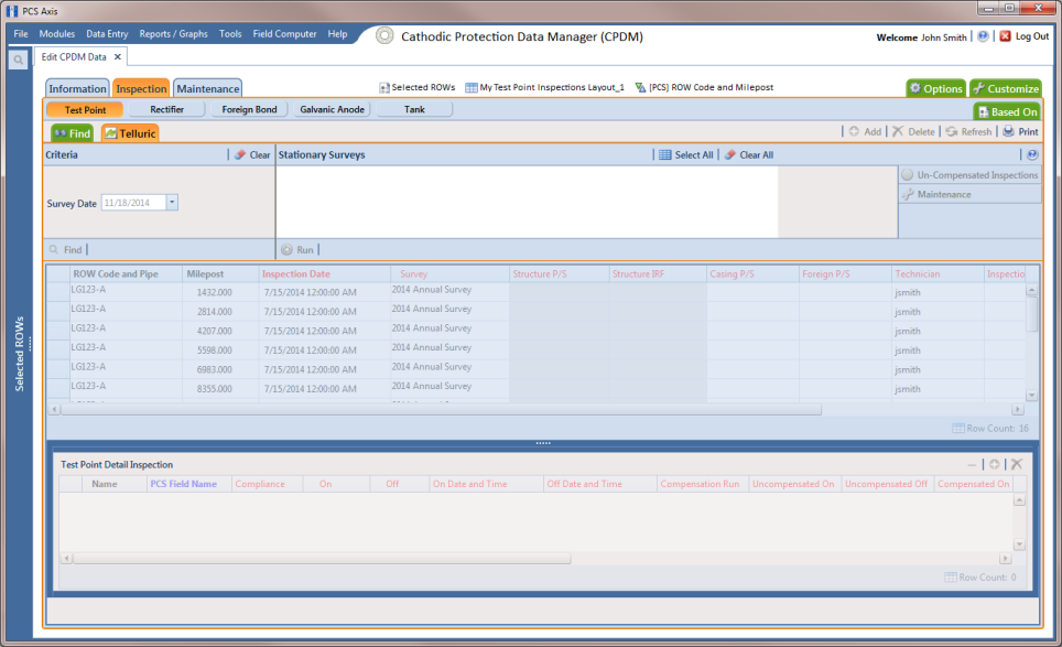
Figure 14-19. Telluric Workspace
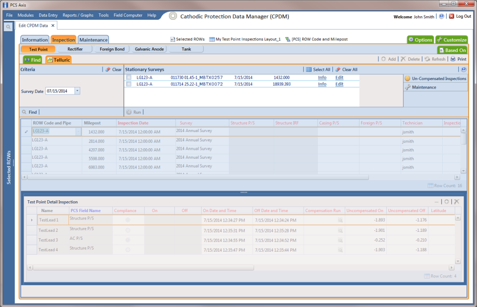
3 Locate the upstream and downstream SDL survey files associated with the selected pipeline segment by clicking the down arrow in the
Survey Date field and selecting a survey date using a calendar. You can also type a survey date in the field using the format MM/DD/YYYY to indicate the month, day, and year. Then click
 Find
Find (
Figure 14-20).
A list of SDL survey files related to the entered survey date display in the Stationary Surveys group box of the Telluric workspace.
4 If you want to view a telluric summary of an SDL survey listed in the
Stationary Surveys group box, click the
Info link to open the
Stationary Telluric Info window. For a description of this window, see
View Telluric Summary Information.
5 If you want to view voltage measurements associated with an SDL survey listed in the
Stationary Surveys group box, click the
Edit link to open the
Stationary Survey Maintenance window. A description of this window is available in the section entitled
Using Stationary Survey Maintenance.
Figure 14-20. Telluric Workspace
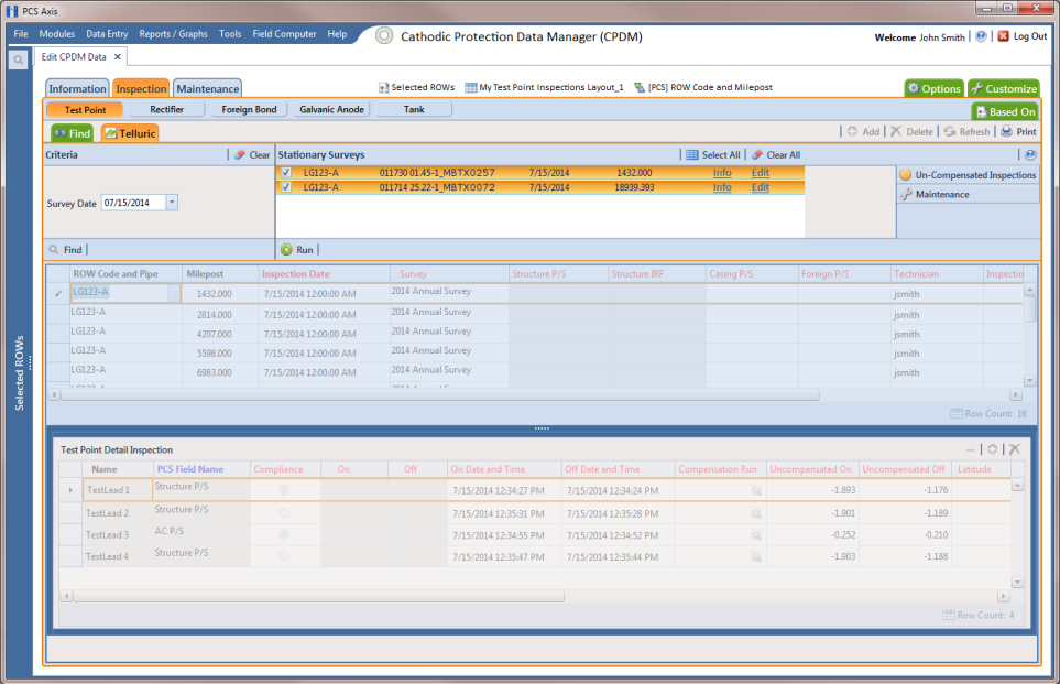
6 To run telluric compensation, follow these steps:
a Select the SDL upstream/downstream data set pair to use in the compensation run. Click the check box associated with the upstream and downstream SDL survey files (
Figure 14-21).
Figure 14-21. Telluric Workspace
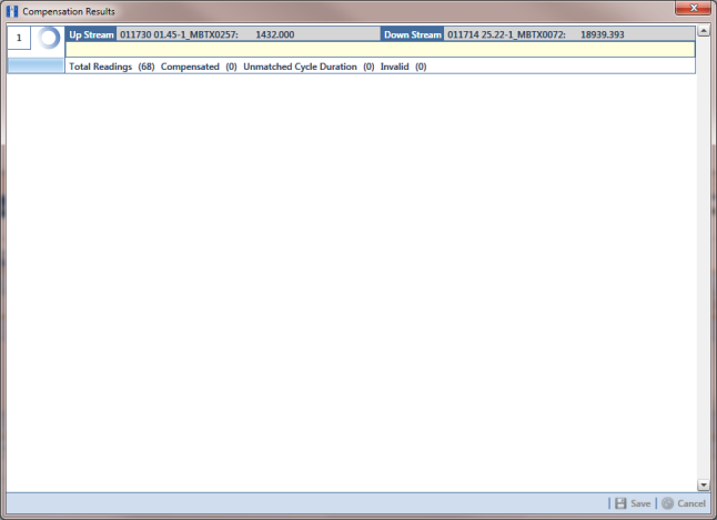
b Click
 Run
Run to begin the compensation process and open the
Compensation Results window (
Figure 14-22).
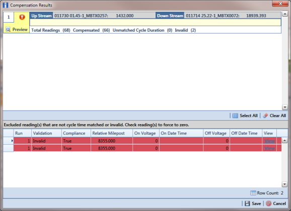
Figure 14-22. Compensation Results
c If an error occurs during the compensation run, a

warning icon displays in the
Compensation Results window. A description of the error and how to resolve it also display.
In the following example, the survey measurement must be changed to zero to apply no telluric correction and successfully run compensation. See
Uncompensating Test Point Inspections for information about how to apply
ForceZero and
Exclude to survey measurements.
Figure 14-23. Warning in Compensation Results
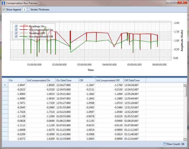
d When the compensation process completes, click
 Preview
 to view a graph of compensation results (
Figure 14-24).
Figure 14-24. Compensation Run Preview
e When you finish viewing the graph, click the

Windows close button to close the graph and return to the
Compensation Results window.
f If you want to apply compensation results to the PCS Axis database, click
 Save
Save in the
Compensation Results window.
Clicking
 Cancel
 cancels the compensation process. PCS Axis closes the window and returns to the
Telluric workspace. Compensation results are also not applied to the PCS Axis database.