Adding a Bridge Import/Export Definition
A Bridge import/export definition specifies the property settings and options for importing and exporting data in PCS Axis. It defines the data transfer options; location of the import file; location for the export file; and mappings for data items in PCS Axis and the import file.
Note: Bridge currently supports use of a facility key only in a Bridge import file. Future enhancements will include use of a facility key in a Bridge export file.
To add a Bridge import/export definition, follow these steps:
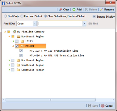
1 Select one or more pipeline segments in the
Select ROWs window. Select pipeline segment(s) with facilities you want to include in the Bridge definition. Click
 Save
Save to close the window (
Figure 10-40).
Figure 10-40. Select ROWs
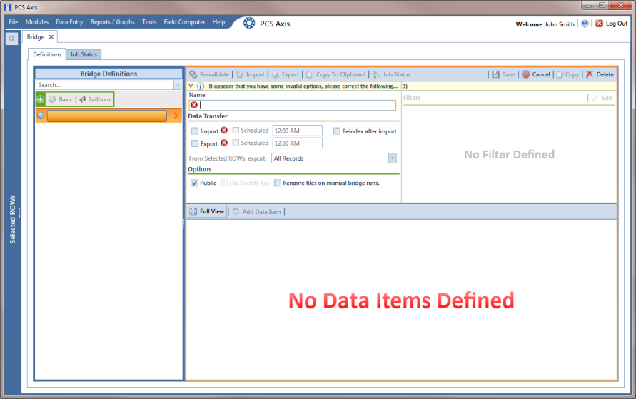
2 Click
Tools >
Bridge to open the
Bridge window (
Figure 10-41)
Figure 10-41. Bridge
Note: Clicking the

toggle button in the

information bar displays important information related to required property settings.
Figure 10-42. Basic Bridge Definition
4 Type a unique name for the definition in the
Name field (
Figure 10-43).
Note: Clicking the Bridge Definitions bar collapses the panel allowing you to view more of the Bridge definition. Clicking the bar again expands the panel.
5 To set properties in the
Data Transfer group box, follow these steps (
Figure 10-43):
a Click the Import and Export check boxes.
b If you want PCS Axis to automatically run the import file at a scheduled time, click the Scheduled check box and then type a scheduled time in the adjacent field. Enter a scheduled time using 12-hour time format to specify the hour, minute, and AM/PM setting (HH:MM AM or PM).
Important: When scheduling a time to run Bridge, choose a time that does not impact other network services or computer resources. For example, consider a staggered time schedule instead of running Bridge at the same time as other scheduled network services.
c If you are importing large amounts of data, click the check box Reindex after import to reindex the PCS Axis database after the import process completes.
Note: Enabling this option prevents index fragmentation from occurring in the PCS Axis database, which in turn may result in slow system performance. Index fragmentation may occur after importing large amounts of data in PCS Axis using Bridge Import, Bullhorn Bridge, or Field Computer. You can also reindex the database using the option Reindex Database in Job Service Viewer (Tools > Job Service Viewer).
d Select which records to export. Click the down arrow in the field From Selected ROWs, export and select an option in the selection list, such as All Records.
6 To set properties in the
Options group box, follow these steps (
Figure 10-43):
a Click the Public check box if you want the import/export definition file available for use by all PCS Axis users. When the check box is empty, the definition file is available only to the user who creates it.
b If you want to use a facility key for facilities in the import file, click the check box
Use Facility Key. This option is not currently available for facilities in the export file. For more information about facility keys, see
Using a Facility Key in Bridge.
When facilities are not mapped to a facility key, they are mapped to the following required fields: ROW Code, Milepost, and Facility ID.
c If you plan to run the import/export file manually and want Bridge to rename the file, click the check box Rename files on manual bridge runs.
Figure 10-43. Bridge Import Export Definition
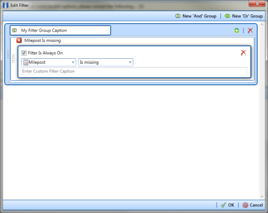
7 If you want to set up one or more filters that apply to
all data items in the definition file, click
 Edit
Edit in the
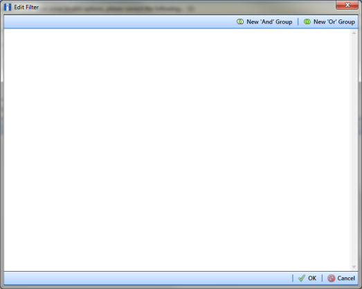
Filters group box to open the
Edit Filter dialog box (
Figure 10-44).
Note: You can also set up one or more filters that
only apply to a selected data item instead of all data items in the definition file. Information is provided later in
step 16.
Figure 10-44. Edit Filter
8 If you want to include a subset of records in the export file that meet all filter conditions, create an AND filter group using the following steps:
a Click
 New ‘And’ Group
 to open the filter properties group box (
Figure 10-45).
b Type a name for the filter group in the field Filter Group Caption.
Figure 10-45. New ‘And’ Filter Group
c Use filter selection fields to set up filter criteria. Select a PCS Axis field, operator, and one or more filter conditions.
d If you want the filter to remain on for all sessions of the data entry grid, select the check box Filter is Always On. When this check box is not selected, toggle the filter on and off in the options page using the filter’s check box.
e Type a name for the filter in the field Enter Custom Filter Caption.
f If you want to set up additional filter criteria for the filter group:
• Click the
 Add
Add button to open another filter properties group box.
• Type a name for the filter in the field
Enter Custom Filter Caption. Then repeat
step 8 "c" through
"e" to set up filter criteria.
9 If you want to include a subset of records in the export file that meet any filter condition, create an OR filter group using the following steps:
a Click
 New ‘Or’ Group
 to open a filter properties group box (
Figure 10-46).
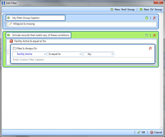
b Type a name for the filter group in the field Include records that match any of these conditions.
c Use filter selection fields to set up filter criteria. Select a PCS Axis field, operator, and one or more filter conditions.
Figure 10-46. New ‘Or’ Filter Group
d If you want the filter to remain on for all sessions of the data entry grid, select the check box Filter is Always On. When this check box is not selected, toggle the filter on and off in the options page using the filter’s check box.
e Type a name for the filter in the field Enter Custom Filter Caption.
f If you want to set up additional filter criteria for the filter group:
• Click the
 Add
Add button to open another filter properties group box.
• Type a name for the filter in the field
Enter Custom Filter Caption. Then repeat
step 9 "c" through
"e" to set up filter criteria.
10 Click
 OK
OK to close the
Edit Filter dialog box and return to the definition window.
Note: Filter settings apply automatically when the Bridge definition is set to run at a scheduled time. When the Bridge definition is run manually, a dialog box opens allowing you to select which filters to apply before running the definition.
11 Click
 Save
Save and then click
 Full View
 to hide the group boxes
Data Transfer,
Options, and
Filters. Clicking
Full View again displays these group boxes.
Note: Clicking the

toggle button in the

information bar displays important information related to required property settings.
12 Select data item(s) you want to import and export. Click
 Add Data Item
 to open the
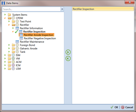
Data Items window and then complete the following steps (
Figure 10-47):
a Open the folder(s) containing the data item(s) you want to import and export. Repeat this step as needed for other folders. For example, the folders CPDM and Rectifier are selected in the next figure.
b Double-click to select a data item and move it to the right pane of the window. Repeat this step as needed for other data items. For example, the data item Rectifier Inspection is selected in the next figure.
Figure 10-47. Data Items
Note: The right pane of the Data Items window lists all selected data items for import. To remove a data item for import, double-click the data item in the right pane to move it back to the left pane.
c Click
 OK
OK to close the dialog box and return to the definition window. Then click
 Save
Save.
13 Identify the location of the import file using the following steps:
a Click the ellipsis button … in the field Import File Name to open the Import File dialog box. Navigate to the import file and then select it.
b Click Open to close the dialog box and return to the definition panel. The path to the import file displays in the field Import File Name.
14 Select a file format and a location to save the export file using the following steps (
Figure 10-48):
a Click the ellipsis button … in the field Export Directory to open the Browse For Folder dialog box. Navigate to a folder on your computer where you want to save the export file. Then click OK to close the dialog box and return to the definition window.
b Type a name for the export file in the field Export File Name. Then click the down arrow in the field Export Format and select a file format for the export file. Options include Excel files (*.xlsx) and Text files (*.txt, *.csv).
c Click
 Save
Save.
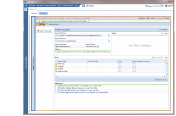
15 If you want to assign inspections in the import file to a survey folder based on the inspection date, complete one or both of the following steps in the
Options group box as required (
Figure 10-48).
a If you want to assign inspections to an annual survey folder, click the check box Assign inspections to an Annual Survey.
b If you want to assign inspections to a periodic survey folder, click the check box Assign inspections to a Periodic Survey.
Figure 10-48. Bridge Import Export
16 If you want to set up one or more filters for the export file that apply only to the currently selected data item, follow these steps:
a If more than one data item is included in the export file, select a data item in the menu on the left side of the window.
b Click
 Edit
Edit in the
Filters group box to open the
Edit Filter dialog box (
Figure 10-49).
Figure 10-49. Edit Filter
17 If you want to include a subset of records in the export file that meet all filter conditions, create an AND filter group using the following steps:
a Click
 New ‘And’ Group
 to open the filter properties group box (
Figure 10-50).
b Type a name for the filter group in the field Filter Group Caption.
Figure 10-50. New ‘And’ Filter Group
c Use filter selection fields to set up filter criteria. Select a PCS Axis field, operator, and one or more filter conditions.
d If you want the filter to remain on for all sessions of the data entry grid, select the check box Filter is Always On. When this check box is not selected, toggle the filter on and off in the options page using the filter’s check box.
e Type a name for the filter in the field Enter Custom Filter Caption.
f If you want to set up additional filter criteria for the filter group:
• Click the
 Add
Add button to open another filter properties group box.
• Type a name for the filter in the field
Enter Custom Filter Caption. Then repeat
step 17 "c" through
"e" to set up filter criteria.
18 If you want to include a subset of records in the export file that meet any filter condition, create an OR filter group using the following steps:
a Click
 New ‘Or’ Group
 to open a filter properties group box (
Figure 10-51).
b Type a name for the filter group in the field Include records that match any of these conditions.
c Use filter selection fields to set up filter criteria. Select a PCS Axis field, operator, and one or more filter conditions.
Figure 10-51. New ‘Or’ Filter Group
d If you want the filter to remain on for all sessions of the data entry grid, select the check box Filter is Always On. When this check box is not selected, toggle the filter on and off in the options page using the filter’s check box.
e Type a name for the filter in the field Enter Custom Filter Caption.
f If you want to set up additional filter criteria for the filter group:
• Click the
 Add
Add button to open another filter properties group box.
• Type a name for the filter in the field
Enter Custom Filter Caption. Then repeat
step 18 "c" through
"e" to set up filter criteria.
19 Click
 OK
OK to close the
Edit Filter dialog box and return to the definition window.
Note: Filter settings apply automatically when the Bridge definition is set to run at a scheduled time. When the Bridge definition is run manually, a dialog box opens allowing you to select which filters to apply before running the definition.
20 Click
 Save
Save.
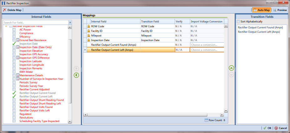
21 To map fields in PCS Axis with fields in the import file, follow these steps:
a Click
 Edit
Edit in the
Maps group box to open a field mapping window (
Figure 10-52).
Note: Fields in the
Mappings panel with a lock icon

are required fields for mapping, such as
ROW Code,
Milepost,
Facility ID, and
Inspection Date shown in the following example (
Figure 10-52).
b Select PCS Axis fields for mapping. Click the

toggle arrow for a field category in the
Internal Fields panel to view a list of available fields. For example,
Rectifier Inspection Fields is selected in the next figure.
c Click the check box for one or more PCS Axis fields listed in the
Internal Fields panel. Then click the

top arrow button to move selections to the
Mappings panel. Double-clicking a field also moves it to the
Mappings panel.
For example, the PCS Axis fields Rectifier Output Current Found (Amps) and Rectifier Output Volts Found (Volts) are selected for mapping in the next figure.
Figure 10-52. Field Mappings
d If you want to sort import fields listed in the Transition Fields panel in alphabetical order, click the check box Sort Alphabetically.
e To map PCS Axis fields with fields in the import file, follow these steps:
• Select a PCS Axis field in the Mappings panel. Map the selected field to a field in the import file by double-clicking a field listed in the Transition Fields panel. Repeat this step for remaining fields you want to map.
Note: When the
 Auto Map
 button is enabled and the names of fields in the import file match those in PCS Axis, double-clicking a PCS Axis field in the
Mappings panel automatically maps to an import field listed in the
Transition Fields panel.
• If the definition is set up to use a facility key, click the Facility Key option button in the Mappings panel for the field you want to use as the facility key, such as ROW Code or Milepost.
• If the field Choose a conversion... is present in the Mappings panel for a pair of mapped fields and you want to apply a conversion option, click the field Choose a conversion ... and select an option in the selection list.
f If you want to preview fields for mapping in the import file, click the
 Preview
 button to open the import file in the
Preview Maps window.
22 Click
 OK
OK to close the mapping window and return to the definition window. Then click
 Save
Save.
Field mappings display in the Maps group box.
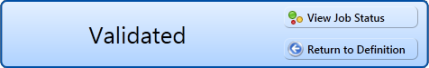
23 To validate the definition, click the
 Prevalidate
 button. When the validation process completes and the following message displays, click
 View Job Status
 or
 Return to Definition
 (
Figure 10-53).
Note: The Prevalidate process confirms the Bridge definition is set up correctly; it does not post data in the database. Only the first 1,000 records of the import file will be displayed.
Figure 10-53. Validated Message
24 If you want to manually import data in PCS Axis, click
 Import
 in the
Definitions window. When the message
Completed displays, click
 View Job Status
 to open the
Job Status window or
 Return to Definition
 to open the
Definitions window.
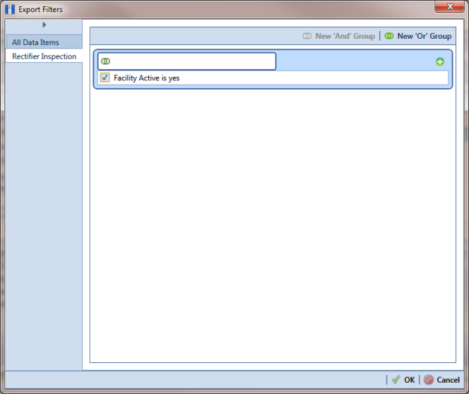
25 To manually export data from PCS Axis, click
 Export
 in the
Definitions window and then complete the following steps to select which filters to apply if the Bridge definition is set up with filters:
a Click the tab
All Data Items. Click the check box for each filter you want to apply to
all data items in the Bridge definition (
Figure 10-54).
b Click a data item tab. For example, the data item tab labeled Rectifier Inspection is selected in the following figure. Click the check box for each filter you want to apply to the selected data item.
Figure 10-54. Export Filters
c Click OK to close the Export Filters dialog box and run the Bridge export file.
d When the message
Completed displays, click
 View Job Status
 to open the
Job Status window or
 Return to Definition
 to open the
Definitions window.
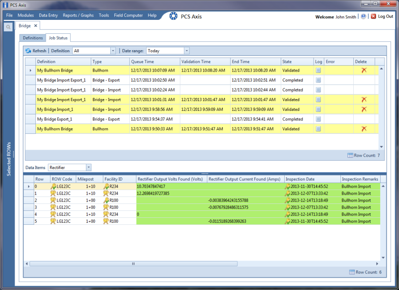
26 To view the status of a Bridge session, click
 Job Status
 in the
Definitions window to open the
Job Status window (
Figure 10-55). Clicking
 Log
Log for a Bridge session opens the log file for the selected session.
Figure 10-55. Job Status
27 To copy the Bridge definition to a file, such as a Notepad or Microsoft Word file, follow these steps:
a Click the Definitions tab if the Definitions window is not open.
b Click
 Copy to Clipboard
.
c Start the software program, such as Notepad or Microsoft Word.
d Open a new file and then Paste the definition file. Click Save.