Adding a Calculated User Defined Field
The procedure in this section includes an example that describes how to define an expression for a user defined field (UDF) labeled Shorted P/S. In the example, if Casing P/S is below protection criteria (less than or more negative than –0.8495), PCS Axis enables Shorted P/S for data entry in the grid. The field is not enabled for data entry when Casing P/S meets protection criteria.
Note: An expression is a logical statement with specific conditions that must be met before PCS Axis enables the field for data entry. Logical statements are either “true” or “false” based on the conditions defined in the expression for the UDF.
To add a Calculated UDF, follow these steps:
1 Click
Tools >
Field and UDF Customizations to open the
Field and UDF Customizations window (
Figure 3-29).
2 If you want to select a grid layout theme, follow these steps:
a Click
 Customize
 to open the
Column Selections dialog box (
Figure 3-32).
b Click the down arrow in Select a Layout Theme and select a theme in the selection list.
c Click
 Save
Save to close the dialog box and return to the
Field and UDF Customizations window.
3 Select an item in the
Properties panel that includes the data entry grid you want to add a UDF. For example, double-click
Facility Surveys >
CPDM >
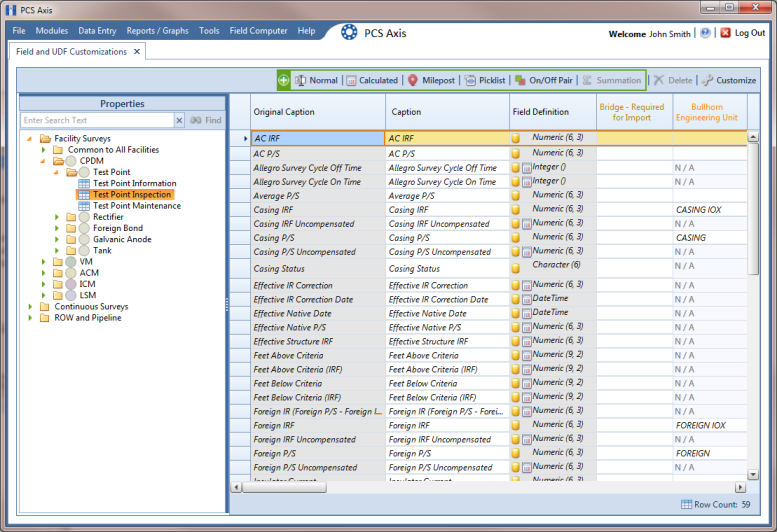
Test Point > Test Point Inspection to display a grid with fields and property settings related to the
Test Point Inspection data entry grid (
Figure 3-38).
Note: Clicking the Properties bar collapses the Properties panel allowing you to view more of the grid. Clicking the bar again expands the panel.
Figure 3-38. Field and UDF Customizations
4 Click
 Calculated
 in the toolbar to open the
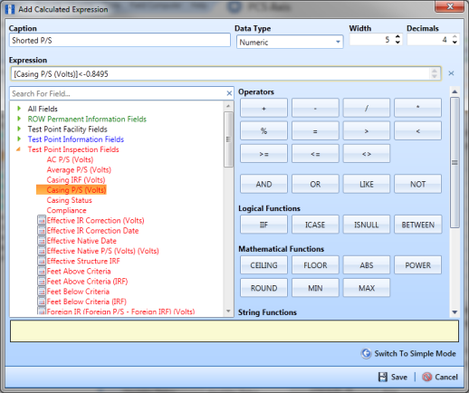
Add Calculated Expression dialog box. If you want to work with the expression editor in advanced mode, click
 Switch To Advanced Mode
 (
Figure 3-39).
Figure 3-39. Add Calculated Expression (Advanced Mode)
5 Type a unique name for the UDF in the Caption field. Then click the down arrow in the Data Type field and select a data type in the selection list, such as Numeric.
6 If you selected the Character or Numeric data type earlier, set the length of the field by typing the number of characters required for the UDF in the Width field. Clicking the up arrow in the Width field increases the value; clicking the down arrow decreases the value.
7 If you selected the Numeric data type earlier, set the number of decimal places required for the UDF by typing a value in the Decimals field.
8 Click a toggle button

to open a field category, such as
Test Point Inspection Fields shown in
Figure 3-38. Double-click a field in the list of fields to add it in the
Expression field. Define the UDF using the operator and functions buttons.
Note: Hovering the mouse over a function or operation button displays a description below the folder tree.
9 Click
 Save
Save to close the dialog box and return to the
Field and UDF Customizations window. The UDF is now available for adding in a data entry grid. If needed, see
Working with Themes and Filter Groups for information about how to add fields in a data entry grid.