Adding a User Defined Module
Information in this section explains how to add a user defined module with one or more user defined facility types. A user defined module supports up to six (6) user defined facility types.
Complete the following steps:
1 Click
File >
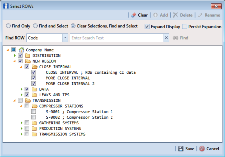
Select ROWs to open the
Select ROWs window (
Figure 3-78). Select one or more pipeline segments and then click
 Save
Save to close the window.
Figure 3-78. Select ROWs
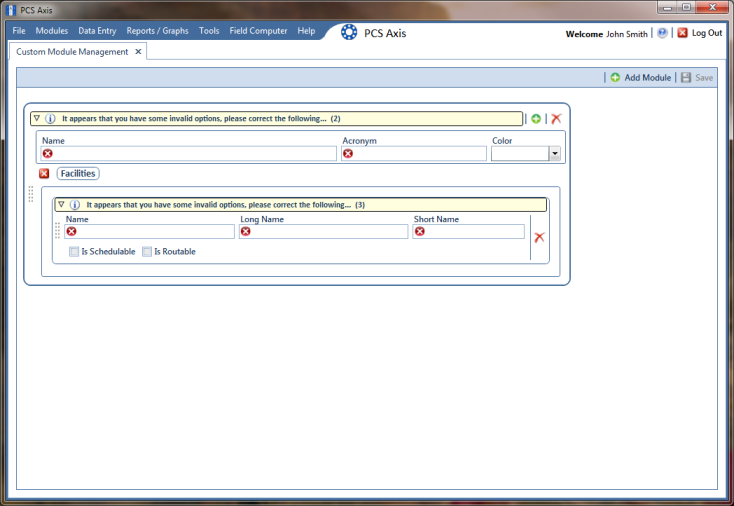
2 Open CMM and add a user defined module. Click
Modules >
Custom Module Management >
 Add Module
 (
Figure 3-79).
PCS Axis adds a group of fields for the new user defined module. Fields with an error icon

indicate a required data entry field.
Figure 3-79. Custom Module Management
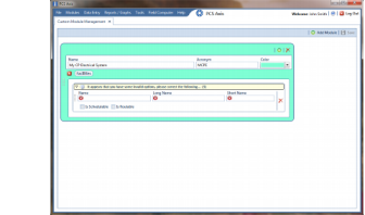
3 To set
Name,
Acronym, and
Color properties for the user defined module, follow these steps (
Figure 3-80):
a Type a name in the Name field. The field accepts up to 50 alphanumeric characters including spaces and special characters.
Note: Clicking the

toggle button in the

information bar displays information related to required property settings.
b Type an acronym in the Acronym field. This field accepts up to four (4) alpha characters. It does not support numeric or special characters.
c Click the down arrow in the Color field and select a color in the color palette.
The following example shows a user defined module with the following property settings: module name is My CP Electrical System, module acronym is MCPE, and module color is Aquamarine.
Figure 3-80. Custom Module Management
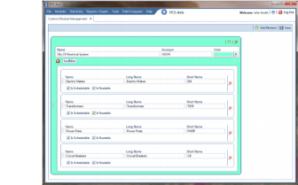
4 To set properties for one or more user defined facility types, complete the following steps (
Figure 3-81):
a Type a name in the Name field. The field accepts up to 30 alphanumeric characters including spaces and special characters. The name you provide appears in data entry grids, reports and graphs, scheduling, routes, and so on.
b Type a longer name for the user defined facility in the Long Name field. This field accepts up to 40 alphanumeric characters including spaces and special characters.
c Type an acronym for the user defined field in the Short Name field. The field accepts up to four (4) alpha characters. It does not support numeric or special characters.
d If you want the facility type available for selection when setting up a schedule, click the check box Is Schedulable. Likewise, click the check box Is Routable to have the facility type available for selection when setting up a route.
The following example shows a user defined module with user defined facility types labeled
Electric Meters,
Transformers,
Power Poles, and
Circuit Breakers (
Figure 3-81).
Figure 3-81. Custom Module Management
e To add another user defined facility type, repeat
step 4 "a" through
"d". You can add up to six (6) user-defined facility types for each user defined module.
f Click
 Save
Save.
Note: Clicking the

close icon in the group box of user defined facility types closes the group box. Use this feature when you only want to view property settings of user defined modules. To re-open the group box, click the

open icon.
5 Click

to close the
Custom Module Management window.
6 Set up the following system features as needed: