Adding and Applying Pipeline Series
The procedure in this section describes how to add a
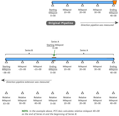
Pipeline Series definition and then apply it to effected milepost numbers in a facility data entry grid. The example in the procedure adds a pipeline extension with negative milepost locations as shown in the following example (
Figure 3-68).
Figure 3-68. Example of an Extended Pipeline with Mileposts Set in Reverse Order
To add and apply a Pipeline Series, follow these steps:
1 Click the
Select ROWs button

to open the
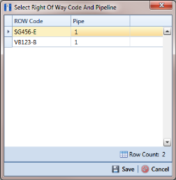
Select ROWs window (
Figure 3-69). Select one or more pipeline segments with facilities you want to work with, then click
 Save
Save to close the window.
Figure 3-69. Select ROWs
2 Select the PCS Axis module you want to work with, such as the CPDM module. Click Modules > Cathodic Protection Data Manager (CPDM).
3 Click
Data Entry >
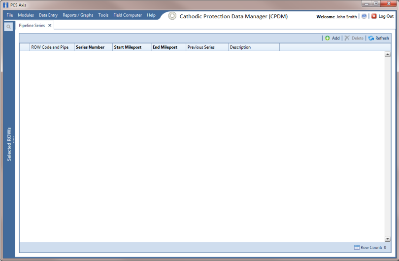
Pipeline Series to open the
Pipeline Series window (
Figure 3-70).
Figure 3-70. Pipeline Series
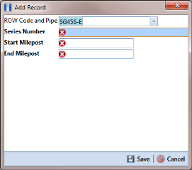
4 Click
 Add
Add and then select the
ROW Code and
Pipe you want to work with in the dialog box that opens (
Figure 3-71).
Figure 3-71. Select Right Of Way Code And Pipeline
5 Click
 Save
Save to display required field(s) for data entry. Required fields are identified with the

icon, such as
Series Number, Start Milepost, and
End Milepost in the next figure (
Figure 3-72).
6 Type a unique identifier for the Pipeline Series in the Series Number field. This field accepts up to 10 alphanumeric characters including spaces and special characters, such as a hyphen (–) or pound sign (#).
7 Set the Pipeline Series start and end milepost numbers. Type the starting milepost in the Start Milepost field and the ending milepost in the End Milepost field.
The starting milepost of the Pipeline Series corresponds to the starting milepost for a segment of the pipeline. The ending milepost of the Pipeline Series corresponds to the ending milepost for the same segment of pipeline.
Figure 3-72. Add Record
8 Click
 Save
Save to close the dialog box and add the record in the
Pipeline Series grid.
9 If you want to add a description or other type of information for the Pipeline Series, type the information in the Description field. This field supports up to 30 alphanumeric characters.
10 If you want to add another
Series, complete the following steps to create a pipeline
Series chain (
Figure 3-73):
b Click the down arrow in the Previous Series field and select the Series that precedes the currently selected series.
c Repeat
step 10 to add additional
Series in the chain as needed.
Note: PCS Axis uses the preceding
Series of each
Series in a chain to calculate the
Relative Milepost. All
Series in a chain except the first
Series require that you identify the
Previous Series (
Figure 3-73).
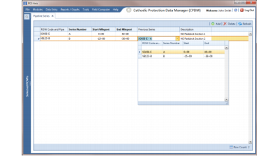
The following example illustrates a pipeline
Series chain with two
Series in the chain (
Figure 3-73).
Series A was added for the original pipeline segment with a start and end milepost of 0+00 and 40+00 respectively.
Series B was added for a pipeline extension. Because the mileposts are in reverse order in
Series B, the
Pipeline Series is set up with a start and end milepost of –38+00 and 0+00 respectively. Also see
Figure 3-71 for an illustration of a pipeline
Series chain with calculated
Relative Mileposts.
Figure 3-73. Pipeline Series
11 Click the

close button to close the
Pipeline Series window.
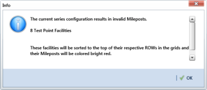
When a message similar to the following example displays, click
 OK
OK to apply pipeline
Series to effected mileposts (
Figure 3-74).
The following message displays to notify you of the facilities that need to have pipeline Series applied in the facility data entry grid. Red facility records in the data entry grid identify milepost numbers that require a pipeline Series applied to the record.
Figure 3-74. Pipeline Series Message
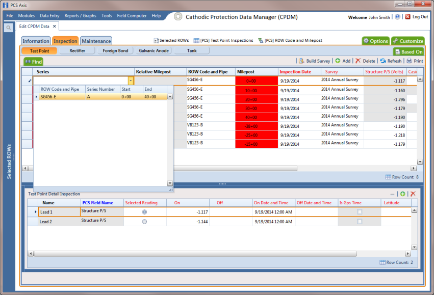
The remaining steps explain how to apply pipeline Series to effected mileposts in a data entry grid.
12 Open the data entry grid with the mileposts you want to apply pipeline
Series, such as the
Test Point Inspection data grid shown in the next example (
Figure 3-75).
Note: Red facility records in the data grid identify milepost numbers that require a Pipeline Series applied to the record.
13 Select the Series field for a facility record in the grid to display a drop-down arrow. Click the arrow and select a pipeline Series in the selection list. Repeat this step for each effected facility record in the data grid.
Figure 3-75. Pipeline Series
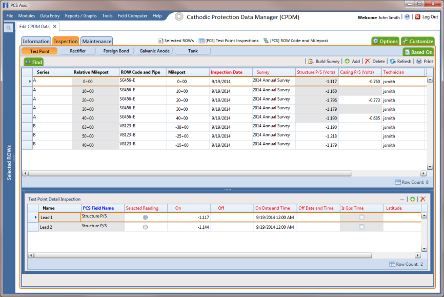
14 Click
 Refresh
 to update data in the grid.
PCS Axis automatically calculates the
Relative Milepost for each facility record assigned a pipeline
Series in the data entry grid. In the following example, PCS Axis calculates relative milepost 40+00 as the end of
Series A and the beginning of
Series B. (
Figure 3-76).
Figure 3-76. Relative Milepost