Adding a Bullhorn Bridge Definition
A Bullhorn Bridge definition specifies the property settings and options for importing data in PCS Axis from a user account on the Bullhorn Asset Tracker (BAT) website. It defines how often to run the definition; the unique Key assigned by BAT to the Extract; and field mappings for PCS Axis and data imported from BAT.
After running a Bullhorn Bridge definition, PCS Axis automatically adds the phrase Bullhorn Import in the Inspection Remarks field of the facility data entry grid.
To add a Bullhorn Bridge definition, follow these steps:
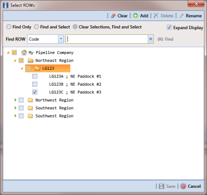
1 Select one or more pipeline segments in the
Select ROWs window. Select pipeline segment(s) with facilities you want to include in the Bullhorn Bridge definition. Click
 Save
Save to close the window (
Figure 10-56).
Figure 10-56. Select ROWs
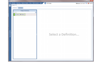
2 Click
Tools >
Bridge to open the
Bridge window (
Figure 10-57).
Figure 10-57. Bridge
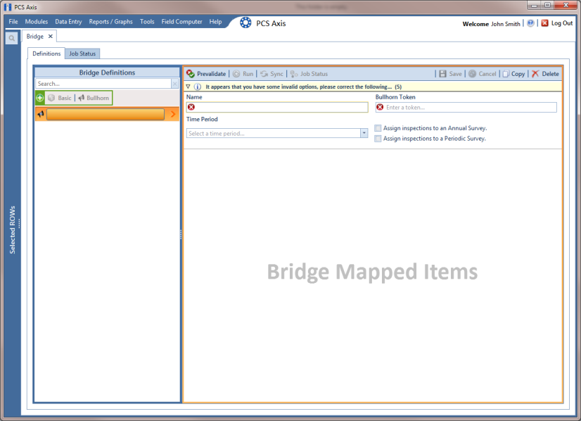
3 Click
 Bullhorn
 to open the Bullhorn definition panel (
Figure 10-58).
Figure 10-58. Bullhorn Definition Panel
4 Type a unique name for the definition in the Name field.
Note: Clicking the Bridge Definitions bar collapses the panel allowing you to view more of the definition panel. Clicking the bar again expands the panel.
5 Click the down arrow in the Time Period field and select how often you want to run the Bullhorn Bridge definition.
Important: When choosing an option in the Time Period field, choose a time that does not impact other network services or computer resources. For example, consider a staggered time schedule instead of running Bridge at the same time as other scheduled network services.
6 Log in to your account on the BAT website and then copy the unique key generated by BAT for the Extract. Paste the unique key in the Bullhorn Token field of the Bullhorn Bridge definition.
7 To assign survey readings to a survey folder based on the inspection date, complete one or both of the following steps as required:
a If you want to assign inspections to an annual survey folder, click the check box Assign inspections to an Annual Survey.
b If you want to assign inspections to a periodic survey folder, click the check box Assign inspections to a Periodic Survey.
Note: Clicking the

toggle button in the

information bar displays important information related to required property settings.
8 Click
 Save
Save and then click
 Full View
 to hide the
Name,
Bullhorn Token,
Time Period, and survey folder fields. Clicking
Full View again displays these fields (
Figure 10-59).
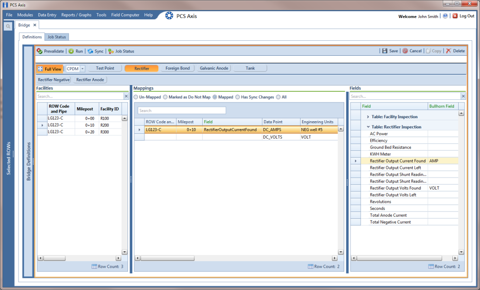
9 Select the PCS Axis module that will receive imported data. Click the down arrow in the module selection list and select a module, such as CPDM.
10 Select the type of facility data you plan to import. Click a facility type button, such as
Rectifier (
Figure 10-59).
11 To map PCS Axis fields with a Bullhorn data point, follow these steps:
a In the center Mappings panel, click the check box Do Not Map for each Bullhorn data point you do not plan to map, such as Battery Voltage.
A check mark inside the check box indicates a selection. To clear a selection, click the check box again to remove the check mark.
Note: Clicking any of the following options allows you to filter records in the Mappings panel based on the selected option: Un-mapped, Marked as Do Not Map, Mapped, and All. For example, clicking Mapped allows you to view only mapped data points in the Mappings panel.
b Select a row in the Mappings panel that includes the Bullhorn data point and engineering units you want to map.
Note: To rearrange grid columns in the
Facilities,
Mappings, or
Fields panel, drag and drop the name of a grid column to a new position. To resize a grid column, place the mouse over a column boundary to change the cursor to a horizontal resize cursor

. Then click and drag the column boundary to resize the grid column.
c In the left Facilities panel, map a PCS Axis milepost to the Bullhorn data point selected in the Mappings panel. Double-click the milepost in the Facilities panel to move it to the Milepost field in the Mappings panel.
Note: Double-clicking a mapped field in the
Mappings panel allows you to unmap the selected field. When a message displays, click
 Yes
Yes to unmap the selected field, or
 No
No to cancel the operation.
d In the right Fields panel, map a PCS Axis field to the Bullhorn Engineering Units field in the Mappings panel. Double-click a PCS Axis field in the Fields panel to move it to the Field column in the Mappings panel.
Figure 10-59. PCS Axis and Bullhorn Mappings
12 When Bullhorn units are added or removed in the unit group set up for the Extract, or the Bullhorn client name changes, click the
 Sync
Sync button to synchronize and update the definition file in PCS Axis.
13 To validate the definition, click the
 Prevalidate
 button.
Note: The Prevalidate process confirms the Bridge definition is set up correctly; it does not post data in the database. Only the first 1,000 records of the import file will be displayed.
14 When the validation process completes and the following message displays (
Figure 10-60), click
 View Job Status
 to open the
Job Status window or
 Return to Definition
 to open the
Definitions window.
Figure 10-60. Validated Message
15 To manually run the definition, follow these steps:
a Click
 Run
Run in the
Definitions window.
b When a date range dialog box opens, specify a date range for the data you want to import from BAT. Type a date in the Start Date and End Date fields or click the down arrow in these fields to select a date using a calendar.
c Click
 Apply
Apply to run the Bullhorn Bridge definition and close the date range dialog box.
d When the message
Completed displays, click
 View Job Status
 to open the
Job Status window or
 Return to Definition
 to open the
Definitions window.
Note: PCS Axis adds the phrase Bullhorn Import in the Inspection Remarks field of the facility Inspection data entry grid.
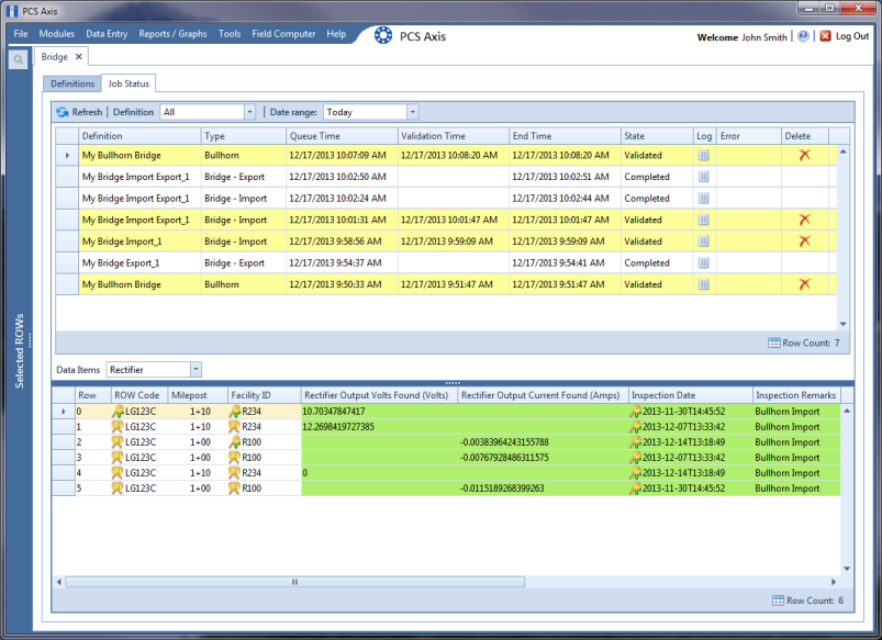
16 To view the status of a Bridge session, click
 Job Status
 in the
Definitions window to open the
Job Status window (
Figure 10-61). Clicking
 Log
Log for a Bridge session opens the log file for the selected session.
Figure 10-61. Job Status
17 To copy the Bridge definition to a file, such as a Notepad or Microsoft Word file, follow these steps:
a Click the Definitions tab if the Definitions window is not open.
b Click
 Copy to Clipboard
.
c Start a text editor or word processor program, such as Notepad or Microsoft Word.
d Open a new file and then Paste the definition file. Click Save.