Adding Inspection GPS Fields in the Inspection Grid
The procedure in this section explains how to add inspection GPS fields in a layout theme and then apply the theme to an Inspection data entry grid. The procedure uses the Test Point Inspection data entry grid as an example.
Complete the following steps:
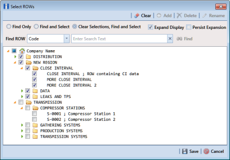
1 Select one or more pipeline segments in the
Select ROWs window (
Figure 8-32). Select pipeline segments with facilities you plan to include in a route. Click
 Save
Save to close the window.
Figure 8-32. Select ROWs
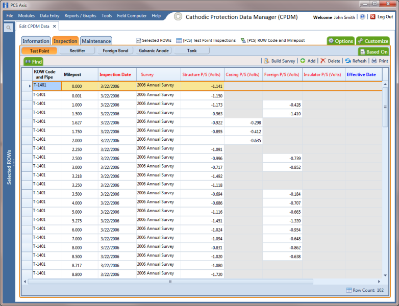
2 Open the Inspection data entry grid for a facility type.
For example, click
Data Entry >
Edit CPDM Data. Click the
Test Point button

, then the
Inspection tab

to open the
Test Point Inspection data entry grid (
Figure 8-33).
Figure 8-33. Test Point Inspection Data Entry Grid
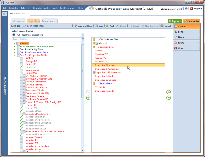
3 Click the
Customize tab

to view the
Layouts page (
Figure 8-34).
Figure 8-34. Layouts
4 Select a data entry grid layout theme. Click the down arrow in Select Layout Theme and select a theme in the selection list.
5 Double-click the
Inspection Fields category in the left pane of the window to view a list of fields available for selection. For example, double-click
 Test Point Inspection Fields
.
6 Add the following inspection GPS fields in the layout theme. To add a field, double-click a inspection GPS field in the left pane to move the field to the right pane. Add other fields as required. The layout theme includes all fields listed in the right pane.
• Inspection Elevation
• Inspection GPS Accuracy
• Inspection GPS Difference
• Inspection Latitude
• Inspection Longitude
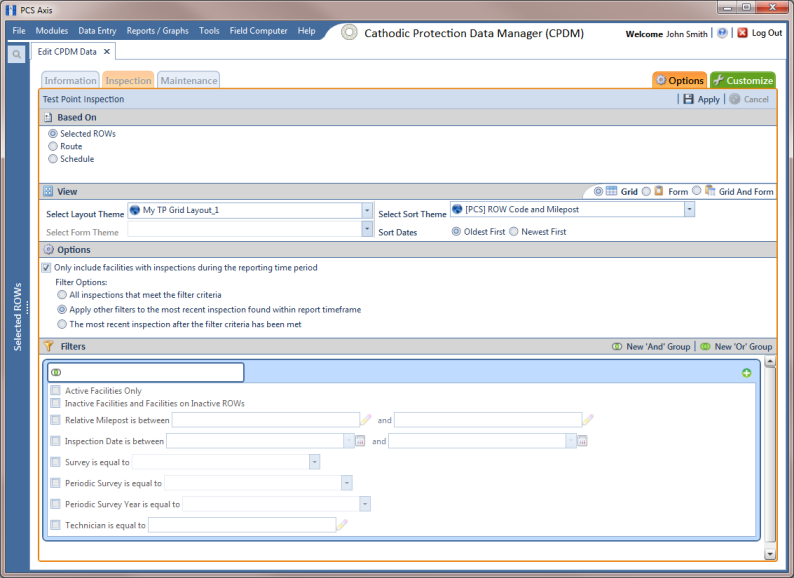
7 Click
 Save
Save, then click the
Options tab

to open the options page (
Figure 8-35).
Figure 8-35. Options
8 Apply the layout theme to the data entry grid. Click the down arrow in Select Layout Theme and select the theme with inspection GPS fields.
9 Click
 Apply
Apply.
PCS Axis saves and applies changes, then closes the options page and returns to the Test Point Inspection data entry grid.