Adding Rectifier Anode Information
To add a record in the Rectifier Anode Information mini-grid for each anode in the ground bed, follow these steps:
1 Click the
Select ROWs button

to open the
Select ROWs window (
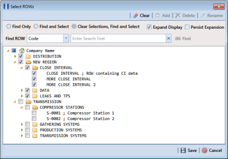
Figure 7-145). Select the pipeline segment(s) with the rectifier you want to work with, then click
 Save
Save to close the window.
Figure 7-145. Select ROWs
2 Open the Edit CPDM Data window. Click Data Entry > Edit CPDM Data.
3 Open the
Rectifier Information grid. Click the
Information tab

and then the
Rectifier button

.
4 If you want to collapse the Selected ROWs panel to view more of the grid, click the Selected ROWs bar. Clicking the bar again expands the panel.
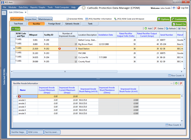
5 Select a row of records in the
Rectifier Information grid with the rectifier you want to add impressed anode records. For example, the record for pipeline segment T-1401 with rectifier R-202 is selected in the next figure (
Figure 7-146).
Figure 7-146. Rectifier Anode Information
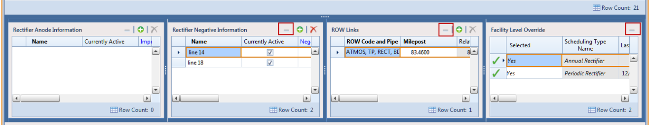
6 If the
Rectifier Anode Information mini-grid is not visible, double-click the
Rectifier Anode... button

at the bottom of the window to open the mini-grid. Click the minimize button

in the upper right-hand corner of any other mini-grid to hide them (
Figure 7-147).
Figure 7-147. Rectifier Information Mini-grids
7 Click
 Add
Add in the
Rectifier Anode Information mini-grid to add an empty record in the mini-grid.
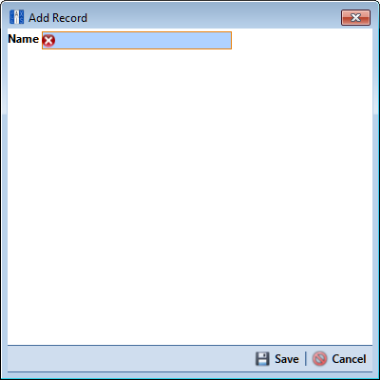
8 In the pop-up
Add Record dialog box (
Figure 7-148), type a name for the anode in the
Name field. Fields requiring information include a

icon. You must enter information in the required fields before the record will be added.
Figure 7-148. Add Record Dialog Box
9 Click
 Save
Save to add the record and close the window.
10 Enter a value in either the field labeled Impressed Anode Shunt Rating or Impressed Anode Shunt Resistance.
Note: If entering a shunt rating, enter it as a mV per A ratio using the format nn.n/nn.n, such as 50.0/25.0 for the shunt rating 50 mV/25 A. If entering a shunt resistance value, enter the actual resistance of the shunt in ohms. When both of these fields are empty, you can enter a value in the field Impressed Anode Shunt Factor instead. Otherwise, PCS Axis automatically calculates the shunt factor based on the value in the shunt rating or shunt reading field.
11 Repeat
step 6 through
step 10 to add each remaining anode in the ground bed.
12 Click
 Refresh
 to update

derived fields, such as
Number of Impressed Anodes. For more information about derived fields, refer to
Working with Derived Fields.
Note: PCS Axis displays the total number of anodes in the system calculated field labeled
Number of Impressed Anodes in the
Rectifier Information and
Inspection grid. This value is based on the total number of anodes in the
Rectifier Anode Information mini-grid. If the field is not present in your grid, refer to
Adding a Data Grid Layout Theme to add the field.