Linking Multiple Subfacilities to a Parent Test Point Facility
The procedure in this section explains how to link multiple subfacilities to a parent test point facility and then select one of the subfacility potential measurements (survey readings) for compliance reporting.
The process begins with adding and linking new subfacility records to a parent test point facility in the Test Point Detail Information mini-grid. After adding these records, they are then available for use in the Test Point Detail Inspection mini-grid.
Complete the following steps:
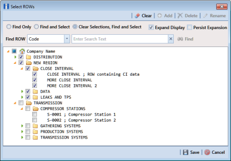
1 Select one or more pipeline segments in the
Select ROWs window (
Figure 7-124). Select pipeline segments with test point facilities you want to work with, then click
 Save
Save to close the window.
Figure 7-124. Select ROWs
2 Click Data Entry > Edit CPDM Data to open the Edit CPDM Data window.
3 Click
Test Point 
and then the
Information tab

to open the
Information grid.
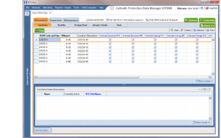
4 If the
Test Point Detail Information mini-grid is not visible, double-click the
Test Point Det... button

at the bottom of the window to open the mini-grid (
Figure 7-125).
Figure 7-125. Test Point Detail Information
5 To add and link new subfacility records to a parent test point facility in the Information grid, follow these steps:
a Select a test point facility in the Information grid.
b Click
 Add
Add in the T
est Point Detail Information mini-grid.
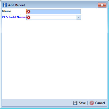
c In the pop-up
Add Record dialog box (
Figure 7-126), type a unique name for the new subfacility in the
Name field. This field supports up to 100 alphanumeric characters. Fields requiring information include a

icon. You must enter information in the required fields before the record will be added.
Figure 7-126. Add Record Dialog Box
Important: To prevent adding duplicate subfacility records in the system, it is important to enter a unique name in the Name field for each subfacility record. Do not use the default name in the Name field or leave it empty (blank).
d Click the field PCS Field Name and select the name of a PCS field. Select a PCS field name that matches the type of potential measurement associated with the new subfacility, such as Structure P/S.
e Click
 Save
Save to add the record and close the window.
f Repeat
step 5 a through
e for each new subfacility record you want to add and link to the currently selected test point facility record.
Note: The Currently Active check box indicates when a subfacility is active or inactive. A check mark inside the check box indicates an active subfacility and can also be included in Prompts sent to the Allegro Field Computer. When the check box is empty, this indicates an inactive subfacility, such as a damaged subfacility or one that has been replaced.
6 Complete the following steps to add potential measurements (survey readings) for subfacilities in the Test Point Detail Inspection mini-grid, and then select one of these for compliance reporting:
a Click the
Inspection tab

to open the
Inspection grid.
b If the
Test Point Detail Inspection mini-grid is not visible, double-click the
Test Point Det... button

at the bottom of the window to open the mini-grid.
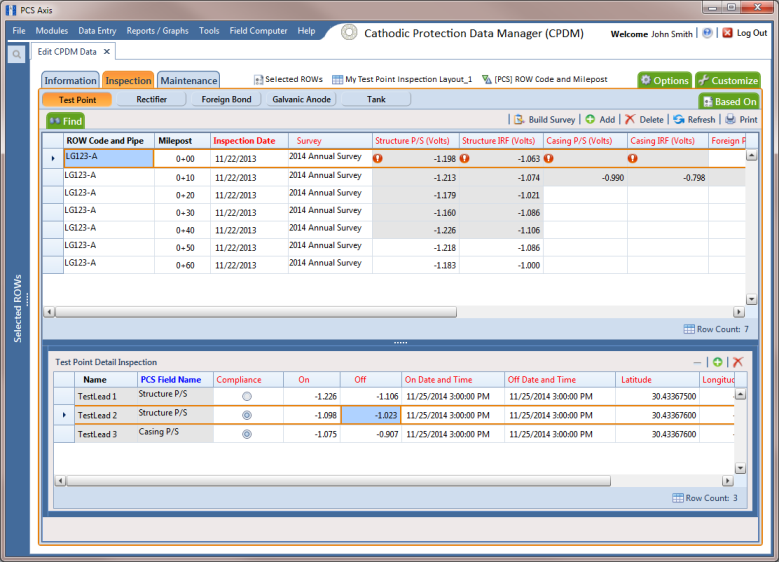
c Select a test point facility in the
Inspection grid that includes subfacilities you want to add potential measurements (
Figure 7-127).
Figure 7-127. Test Point Detail Inspection Mini-Grid
d If potential measurements have not previously been added in the mini-grid, click
 Add
Add to enable the mini-grid for data entry.
e Select a subfacility in the mini-grid. Then add potential measurements and other related survey data in appropriate mini-grid fields. Repeat this step as needed for other linked subfacilities in the mini-grid.
f To select a potential measurement to use for compliance reporting, click the Compliance option button in the mini-grid associated with the subfacility record.
g Based on your PCS Axis license, the Compliance field may be named Selected Reading instead.
h Click
 Refresh
 to copy the selected potential measurement to the linked test point facility in the
Inspection grid.
i When a value for a dependent field has been updated in a data entry grid, a

notification icon displays in the derived field indicating the value has changed and the data entry grid should be refreshed. Clicking the
 Refresh
 button updates all derived values and removes the notification icon. See
Working with Derived Fields for more information.